Chromatography
Published over 4 years ago. See the latest and most current information on Chromatography.
The help desk has historically not written much about the challenges associated with gas chromatography. Although GC is a robust technique, it is still prone to issues and for this edition of the chromatography help desk we will look at one area which can cause gas chromatographers a large amount of angst.
The focus for any investigation for GC tends to focus on the injector and the issues that can arise due to poor set up of the injector. The injector is a key component of the gas chromatograph and incorrect installation of the various components can result in a range of different issues that the separation scientist will have to resolve. The most common issue associated with the injector is that of incorrect setting of the temperature which can result in;
• Septa bleed
• Discrimination between different molecular mass components of the sample.
• Decomposition of the sample.
• A drop off in the signal intensity for all of the peaks associated with the sample.
• Split peaks due to cold spots within the injector
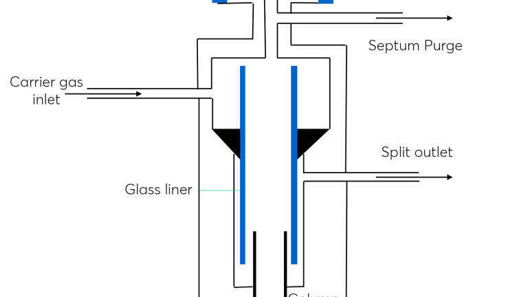
Figure 1 shows a typical arrangement for a GC injector. The principal function of the injector is to transfer liquid samples via a heated inlet, causing the sample to vaporise, mixing with the carrier gas and then be transferred onto the column. This design was brought about due to the development of capillary GC, which allowed for much greater efficiency in separations but where two fundamental problems were introduced to the experimental arrangement.
• The syringe no longer fitted into the column, which previously had been a relatively large (1/4 or 1/8 inch diameter) packed GC column. It is appreciated that on column injections can be made, but at the time of introducing capillary GCs there was a lack of suitable technology that allowed for this to occur.
• The available surface area in a capillary open tubular column is significantly less than that of a packed column, which results in substantial overloading issues of the column when >1 μL of sample is injected directly onto the column.
Figure 1. Schematic diagram of a split/splitless injection port.
The solution was to remove part of the original sample inside the injector unit via a split flow mechanism. This greatly increased the complexity of the injector pneumatics, and also resulted in detection issues as less sample was reaching the detector. There are other injection techniques that can be utilised with GC, however this article will focus on the split/splitless injector, although it is noted that the use of cold on column will alleviate some of the challenges that are discussed here.
The sample will typically be in a vial and then prior to injection transferred to a syringe immediately prior to the injection process. There are issues associated with the process in ensuring that the sample remains intact, and consistent with the sample that was originally taken. Sample component loss from the vial, can occur due to adsorption of an analyte on an activated surface or due to evaporation caused by an ill-fitting closure, or inappropriate use of a particular septa. Assuming the sample integrity is maintained within the sample vial and transferring to the syringe, the next consideration is moving the sample into the injection port.
This requires the needle to typically go through a septa into a heated port. This means that the selection of the material for the septa becomes a critical decision, since the septa will be pierced many times before it is replaced. If the material is too hard then this could result in needle damage or coring of the septa. It is also important not to overtighten the septum nut, which can result in the same effect occurring. Coring is when tiny particles of the septa are broken off during the injection process, and these can transfer to the injection port and even the column, resulting in contamination or potential blockages. It should be noted that it is also important not to under tighten the septa nut as this could result in a loss of sample through the septa.
The injection port is heated to ensure that volatilisation of the sample occurs and that the individual components are in a gaseous state. There are a range of temperatures that are utilised ranging from just above room temperature up to 450°C, the higher the temperature the more likely components within the septa will bleed into the injection port, and the use of temperature gradients within the injector port may result in a build-up of bleed components, that effectively get reinjected on the next injection cycle. These components, such as silicone oils or phthalates, are used in the manufacturing process. Septa bleed can be alleviated by a variety of approaches.
• The use of a septum purge which will sweep gas from behind the septa to remove the bulk of any thermal degradation components coming from the septa.
• Thermally condition the septa for a couple of hours prior to use.
• Use specifically designed high temperature septa. These septa may not be applicable for low temperature use however as they will not be as pliable as the lower temperature use septa.
If there is bleed occurring this can result in ghost peaks or an elevated baseline, Figure 2.
Figure 2. Schematic of a ghost peak.
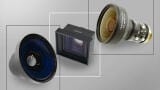
The construction of the injector means that the sample is introduced into a space that is surround by a liner. There are a myriad of different available GC injector liners available, all of which are designed for specific sample types and also types of injections, some of which are shown in Figure 3. It is important to have an understanding of what the liners do and also the impact of choosing the wrong liner can have for an application.
The role of the liner in a GC system is to form a vessel into which the sample can be injected and heated. This enables rapid, uniform vaporisation of the sample and efficient transfer onto the head of the GC column as a tight band, without any adsorption effects. If the transfer onto the column is not efficient then this can result in peak tailing. For a split injection and also where temperature programming is used such as in a PTV (Programmable Temperature Volatilisation) injector the transfer takes place over a longer time period. With these latter injection techniques, the aim is to transfer each target analyte onto the column as a narrow band and not the entire sample.
Figure 3. A small selection of the myriad of iGC injector liners that are available.
GC injector liners used for a split injection are typically open ended at the bottom which enables the split flow to pass across the bottom of the liner removing a portion of the sample allowing a split injection to be performed.
Splitless liners are typically tapered at the bottom with the column inserted into the taper. This helps to funnel the sample onto the column and minimises sample contact with reactive metal components in the inlet during the time the split flow is off during splitless injection.
On entering the injection port the sample will be vaporised, the first part of this process is the formation of a aerosol, which then will become gaseous due to the high temperatures in the injector port area. It is important that the aerosol does not reach the column before it becomes a gas and so a deactivated quartz wool is often used to aid the volatilisation process by increasing the available surface area over which the heating can occur. This improved vaporisation gives more reproducible injections with little boiling point discrimination.
The deactivated quartz wool can be positioned so that the injection needle injects above it, or that the injector need injects into the quart wool, with the latter there is the advantage that the syringe is wiped clean after an injection. The quartz wool will also trap any particulates from the sample, however this may cause carryover, and so the quartz wool should be replaced on a regular basis.
With the development of the split injector the physical manipulation of the sample can also cause an issue with the equal delivery of sample components onto the column and so it is feasible for discrimination to occur at the injector port. This can occur within the syringe as the sample is being transferred across to the injection port and also within the injection port itself. In all cases it is the different rates of volatilisation of the sample that cause the discrimination issue.
As the sample leaves the syringe the more volatile components will preferentially move into the injector port first, whereas there is a tendency for the low volatile components to be left in the needle tip. As the sample enters the injection port the more volatile components will be swept away easier than the less volatile components. Overall, it is the latter effect that has a tendency to be most prevalent and so as a consequence the injector can result in the concentration of heavy molecular weight components entering the column being less than in the original sample. This is typically overcome by the use of introducing a large surface area component into the injector, such as quartz wool, as described previously. One approach that has been developed to address this is the use of a ‘hot needle’ injection where the needle is heated in the injection port for a few seconds prior to injection.
If a PTV is being used, which has a smaller volume, then the use of a baffled injection liner can help since the baffles create a turbulent flow improving sample mixing in the inlet improving injection reproducibility. This type of liner may not be suitable for samples with high boiling points as incomplete vaporisation can occur.
An increase in the available surface area also highlights two other potential issue that can occur within the injector port, namely
• Loss of analyte due to adsorption
• Conversion of an analyte to another species
It has been discussed at length within liquid chromatography the issue that the underlying silica can have on the retention mechanism, in particular for basic components. A similar consideration occurs when injecting reactive components when using GC. The available surfaces that are exposed within the injector will be highly dependent on the type of liner that is used, and also the design of the gas chromatograph. Exposed metal will be reactive to a wide range of components and it is important when using a split injection mode that this is minimised, and the use of a tapered liner can help substantially here.
It is also possible for the high temperature and reactive surfaces to create an environment where the analyte undergoes a chemical change within the injector.
The classic example of this is when analysing chlorinated pesticides, such as Endrin and DDT (dichloro-diphenyl-trichloroethane) which are designed to breakdown, to avoid accumulation within the environment. In a heated environment this breakdown process can be increased dramatically, in particular, if there is an active surface where surface catalysis of the reaction can occur. Figure 4 shows some of the products that can be formed under the wrong conditions within the injector for DDT.
Figure 4. Degradation products of DDT.
Once the physical arrangement for the injector has been optimised it is important to set up the temperature and also the gas flows. On a split injection the split ratio is defined as the ratio of the flow of gas going to waste compared to the amount of gas going onto the column. The ratio will be dependent on a range of factors including.
• Sensitivity of assay
• Required chromatographic efficiency
• Discrimination effects
Typical ratios will be 30:1 up to 100:1, where the higher number represents the proportional amount of gas going to waste.
The other parameter that has to be set is the injector temperature. The injector temperature should be set high enough so that volatilisation of the sample occurs, however not so high that sample degradation occurs. It should be noted that within the injector of a standard split/splitless injector there will be a temperature gradient going from the septa nut, which will be lower that the central part of the injector down to the column, which will typically also be lower than the central part of the injector temperature.
Finally, Table 1 gives a summary of the different types of injectors available for a GC with an overview of the features and challenges associated with each technique.
Table 1. Summary of feature and challenges associated with a range of GC injection techniques.
Automation of the GC injector process has helped to classify gas chromatography as an established technique where there is a perception that there is little new technological developments is to be discovered, or where the challenges associated with the technique have all been addressed. As with much of the separation science world this is absolutely not the case and the developments in GC will continue to improve the chromatographic performance and the applicability of the technology. With the introduction of new technologies, the understanding of the challenges associated with the different components, such as the injector become significant in ensuring that we do not reinvent the same issues that we have observed previously.
For readers who are interested in learning more in this area then there are some excellent texts by K. Grobb.
1. K. Grobb, Jr., J. Chromatogr. 279 (1983) 225-232
2. K. Grobb, Anal. Chem. 66 (1994) 1009-1019A
3. K. Grobb, Split and Splitless Injection for Quantitative Gas Chromatography Concepts, Processes, Practical Guideline, Sources of Error, 4th ed. Wiley New York (2001)
4. K. Grob, G. Grobb, J. Chromatogr. Sci. 7 (1969) 584
ILM 51.5 July 2026


.jpg)
.jpg)


-(1).jpg)