Chromatography
When purifying proteins and other actives in production or research environments the aim is to achieve the purest possible compound with the highest yield to ensure the preparation is cost effective. FPLC (Fast Protein Liquid Chromatography) uses the principles of chromatography to separate the target molecule from the remaining ingredients or compounds present in the reaction mixture. A good separation allows for a fraction of the chromatographed material to be collected increasing yields and removing contaminants. However, when you are trying to separate closely related compounds then this fraction may have to be separated using a different separation mechanism to ensure the best purity. This can mean using two FPLC systems with different chromatography set ups which can slow production and increase costs. This article shows that setting up an FPLC system and using Two Step Purification can enable a single system to produce high yields and purities with a single run.
Two step purification is a special multicolumn chromatography solution. Two independent methods, each with their associated specific column, are used to realise the purification of the target molecule without manual interference. The principle here is that the protein sample is applied on the first column. During elution of the protein, the protein peak is detected triggering the collection of the eluted protein in a storage loop or storage vessel/container. The protein is then automatically applied on the second column to further enhance the quality and or purity of the purified protein. Several systems set ups can be used to automate the purification. In this Technote a two-step purification with the sample pump set up is discussed.
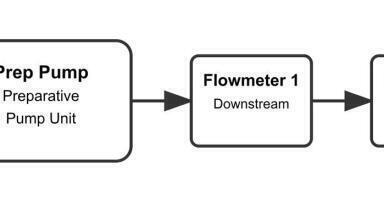
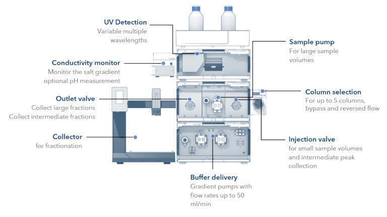
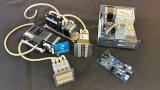
The FPLC system is set up as in Figure 1. A sample pump or simple injection valve is used to introduce the samples to the separation system. Gradient pumps are used with flow rates of up to 50 mL/min. Detection in this article is with UV detection and a conductivity monitor is used to monitor the salt gradient. Fraction collection can be undertaken with either a valve or a fraction collector for more smaller volumes. The essential module for two step separation is the column selection valve which enables the system to change between stationary phase / separation mechanism without the intervention of the scientist.
Figure 1: Typical components of an FPLC system for automated 2 step separation.
The sample pump is used to apply the sample on the first column. The peak eluting from the first column is collected in the sample loop of the injection valve and redirected to the second column. This set ups allows the loading of large sample volumes and minimises the risk of cross contamination during first peak collection because the sample loop is only used for the eluting peak. The injection of small sample volumes is not supported (Figure 2).
Figure 2: Flow scheme for the sample pump set up for two step purification.
The column selection valve is placed between the multi-injection valve and the UV detector. The column outlet port (Col) of the multi-injection valve is connected via a PEEK capillary with the inlet port (IN) of the column selection valve. The outlet port (OUT) is connected to the UV detector flow cell, which in turn is connected to the conductivity monitor. The columns are installed according to Figure 3.
Figure 3: Connection of the column selection valve.
The outlet valve is placed between the conductivity monitor and the fraction collector. The conductivity monitor is connected via the PEEK capillary with the middle port of the outlet valve. Port 1 of the outlet valve goes by default to the fraction collector or waste container. Port 3 to 8 can be used for the collection of large fractions. Port 2 (reinjection) of the outlet valve is connected to the syringe port (Syr) of the multi-injection valve (Figure 4). The syringe port is no longer accessible for sample injection.
Figure 4: Connection of the outlet valve.
Setting up a method for two step purification requires a logical progression of the target compound through the system adjusting the system in a systematic way to allow the most effective separation.
In this example the first step a 1 ml ion exchange column and in the second step a 5 ml Desalting column was used. The sample pump with an air sensor is used for automatic sample application. A 2 ml sample loop was used for intermediate peak parking.
Two separate methods were written for the two columns.
Figure 5: System diagram for the Ion Exchange method during the automatic sample injection.
First, the changes in the flow path are depicted in the flow scheme (Figure 5) and important aspects of the ion exchange method with automatic sample application are highlighted.
The sample is automatically applied via the sample pump. Therefore, the flow of the sample pump is set to 1 ml/min (Figure 5 Section 1) and the multi-injection valve switches to direct injection (Figure 5, Section 2). Make sure to choose the correct column in the beginning of the method (Figure 5, Section 3) and that the column is equilibrated with buffer A. During automatic sample injection the wait function is used to detect the end of the sample application via the air sensor (Figure 5, Section 4).
Figure 6: System Diagram after sample application.
When the sample application is finished, the sample pump is turned off (Figure. 6, Section 1) and the system pump starts running (Figure 6, Section 2). The multi-injection valve is switching to the Manual Load position (Figure 6, Section 3). After an isocratic washing step, the elution starts after 5 ml with the beginning of the gradient.
To recognise the eluting peak two threshold functions are used. The thresholds are active during the gradient elution. Once a peak above 100 mAU is detected (threshold ‘Peak Storage Start’), the peak is rerouted to the sample loop. For this the outlet valve switches to the reinjection position (Figure 7, Section 1). The multi-injection valve was already in the manual load/reinjection position. If the peak is below 100 mAU (threshold ‘Peak Storage Stop’) the outlet valve switches back to collector. The annotation in the threshold function is used to mark the start and stop of the peak storage in the chromatogram. Please keep in mind to program an execution delay for the delay volume between the UV detector and the outlet valve for ‘Peak Storage Start’ and an execution delay for the delay volume between the UV detector and the multi-injection valve for “Peak Storage Stop”. At the end of the run purified protein is stored in the injection loop and can be further purified via the second column in the next step without manual interference.
Figure 7: System diagram during collection of intermediate peak.
Figure 8: System Diagram for Desalting method during system wash.
After the ion exchange method, the desalting method starts. First, the system and the tubing are primed with buffer used for the desalting step. The conditioning is used to wash the system at a flowrate of 2.5 ml/min with buffer A2 (Figure 8, Sections 1,2) for 1 minute. The column selection valve is in the bypass position (Figure 8, Section 3).
Figure 9: System Diagram of Desalting method.
After conditioning the system, the desalting step starts. Therefore, the column changes (Figure 9, Section 1). To inject the intermediate peak onto the desalting column the multi-injection valve is set to the inject position (Figure 9, Section 2). The eluting peak is precisely fractionated with the help of the threshold function (Figure 9, Section 3) using the fraction collector. At the end of the two-step purification run the protein is purified and collected in small fractions
To run both methods one after the other a sequence table is used. To enable this an additional washing and re-equilibration step must be run between samples for the Ion exchange column, but this is not detailed in this article.
This article explains the basic set up of a two-step separation using a basic FPLC system enabling higher yields and sample purity. The automated nature of this type of purification allows the scientist to walk away from the system during the purification process once initial method development is completed. All parameters of the separation model can be adjusted to maximise the yield using standard chromatographic method development and adjusting timings for the second separation.
This article is based on work carried out by Ulrika Krop and Kate Monks of Knauer
Knauer Wissenschaftliche Geräte GmbH, www.knauer.net.
The purification was run and developed on a Knauer Multimethod FPLC system which was set up for bio-chromatography methods with an additional sample pump.
Verulam Scientific are the UK official distributor and service provider for KNAUER,
please direct any enquiries to [email protected] or call 01234 381000.
ILM 51.5 July 2026


-(1).jpg)
.jpg)